Tuesday, 8 May 2012

Grogley Junction - Another idea

Since coming back from Cornwall I’ve been thinking about my Grogley Junction project. Spending time on the Camel Trail walking the line from Grogley Junction to Polbrock and beyond has really fired my imagination for the project.

In my collection of photographs of the line I have one of an O2 passing in front of some cottages with the river Camel in the foreground. To me it is one of those photographs that, along with photographs of Beattie Well tanks passing between the cottages at Hellandbridge, typifies the feel of this line. Until my visit to the location I could not place where the photo was taken as it is constantly referred to as being at Grogley. In fact the cottages are Grogley side of the road-over bridge at Polbrock. Finding the location and discovering from Andrew Jones survey that there was a continuous check rail though the reverse curves leading to the Polbrock road bridge, made me question whether I could include this section of line in my model of Grogley Junction. Unfortunately I would need something like 60 feet in length to model the whole section of line from Grogley to Polbrock in 4mm.


Considerations I’ve been trying to take into account over the last few weeks are: how far I want to bend history to suit my own ends; how much time the project might take; and the space I have available. As it seems to be taking me an eternity just to complete a little test track it would seem any grandiose plan of a large junction station with freight marshalling yard is way beyond my capabilities, not just in the space I have available, but also time I would have to get the model to an acceptable stage of completion in my life time.

Part of my time on the Camel Trail was spent photographing the bridges at Boscarne with thoughts that I might end up building a model of Boscarne Junction. Other thoughts have taken me to consider using the track layout at Boscarne Junction as a template for my Grogley Junction. This would mean that, in my alternative universe, Grogley Junction will be worked in a similar way to Boscarne Junction but with the addition of a few sidings. The extra sidings would be used for the marshalling of goods traffic for the different branches radiating from Grogley. If all goes well, the space I could have available to build this model is 23ft x (just under) 9ft. Taking off about 4ft each end for hidden sidings leaves me 15ft in length to try and do this fictitious junction justice.


Above is my initial attempt. The area that I've mapped out is drastically compressed in length and width compared to the actual location. I've also hacked a large section out between Grogley and Polbrock to bring the cottages, in the above photo, into the area to be modelled. I would be trying to replicate the scene in the photograph above looking from point A on the plan. After all the compression the hope is that the model can capture the feel of the valley and it would still be recognisable as Grogley/Polbrock. I'm also hoping I don't offend the locals too much with the butchering of their landscape...

The numbers on the plan are the metric heights above sea level. The track bed is about 10 metres above sea level. In 4mm scale the highest point at the back of the model would be about 20 inches above the track. At the front each side rise to approximately 7 inches. In the centre of the model the viewed is over the river and meadow to the track on a small embankment. The baseboard width is about 4.5 ft and, with the reverse curvature, will no doubt cause me some headaches to build.

So is this it...?  I doubt it, as the above is still a very rough and no doubt over the course of the next year I'll be reworking the plan many times while I'm trying to prove my modelling capabilities with Tredethy Wharf. The applying of information learnt from Andrew's survey in 1972, rail lengths, type of chairs and sleepers per length, into the track plan will also need to be undertaken. I also realise I have a lot to learn about the goods workings in the area and how my fictitious spin on the line would affect these workings and the need for the extra sidings.

Grogley Junction might still be a 'pipe dream', however, I do like the feel of the above plan and in my head it is creating some great images. I've now just got to stop dreaming/planning and get on with Tredethy Wharf...

Saturday, 5 May 2012

One Gremlin banished

One of the little Gremlins that surfaced when testing Tredethy Wharf was the in continuous check rail area where a road will cross the track. For some reason I purchased S4 plastic check rail chairs instead of P4 which caused some slight wheel binding on a converted Pannier Tank in this section of track.


As all of this section will be fully covered I decided to try and solve the problem by relaying this section using copperclad sleepers. A sharp knife blade was slid between the plastic chairs and the wooden sleeper and the rail removed. Copperclad sleepers were then laid between the wooden sleepers. The rail was cleaned and then relayed with some very crude soldering. Some advice I'd been given was, as this section is to be covered, to double gap the copperclad sleepers as a 'belt and braces' against electrical shorts.


After a brief test I think I've sorted it... Should have laid this section in copperclad from the start.

Wednesday, 2 May 2012

Winter Project - Gearbox

The holiday (or should I say field trip) in Cornwall and the hasty day at Scalefour North has renewed my enthusiasm for all things P4 and Grogley Junction. Over the weekend I found a couple of hours to build the High Level gearbox. The gearbox came with very comprehensive instructions, which, at first, make the construction look complicated. But when all the components were all laid out on the table and each paragraph was read a couple of times, the mist started to clear and the gearbox was very quickly assembled.


After a quick test under power it was soon installed in the chassis and it is starting to look promising... Oh and it moves!!...


I think the next task will be to create a cradle to support the motor and work out how to install the pick-ups.


Tuesday, 1 May 2012

Buffer Stops (part 3)

I think I've solved the mystery of how the buffer stop at Dunmere Wharf might have been constructed. Below are a few photos of the current buffer stop at Boscarne on the Bodmin & Wenford Railway. Apart from Dunmere buffer stop having a wooden buffer beam this one seems to be very similar to the photos in my previous posting on buffer stops here.


These photos help to resurrect the idea that this style of buffer stop could be installed on my Tredethy Wharf...

Saturday, 21 April 2012

Spring Steam Spectacular 2012

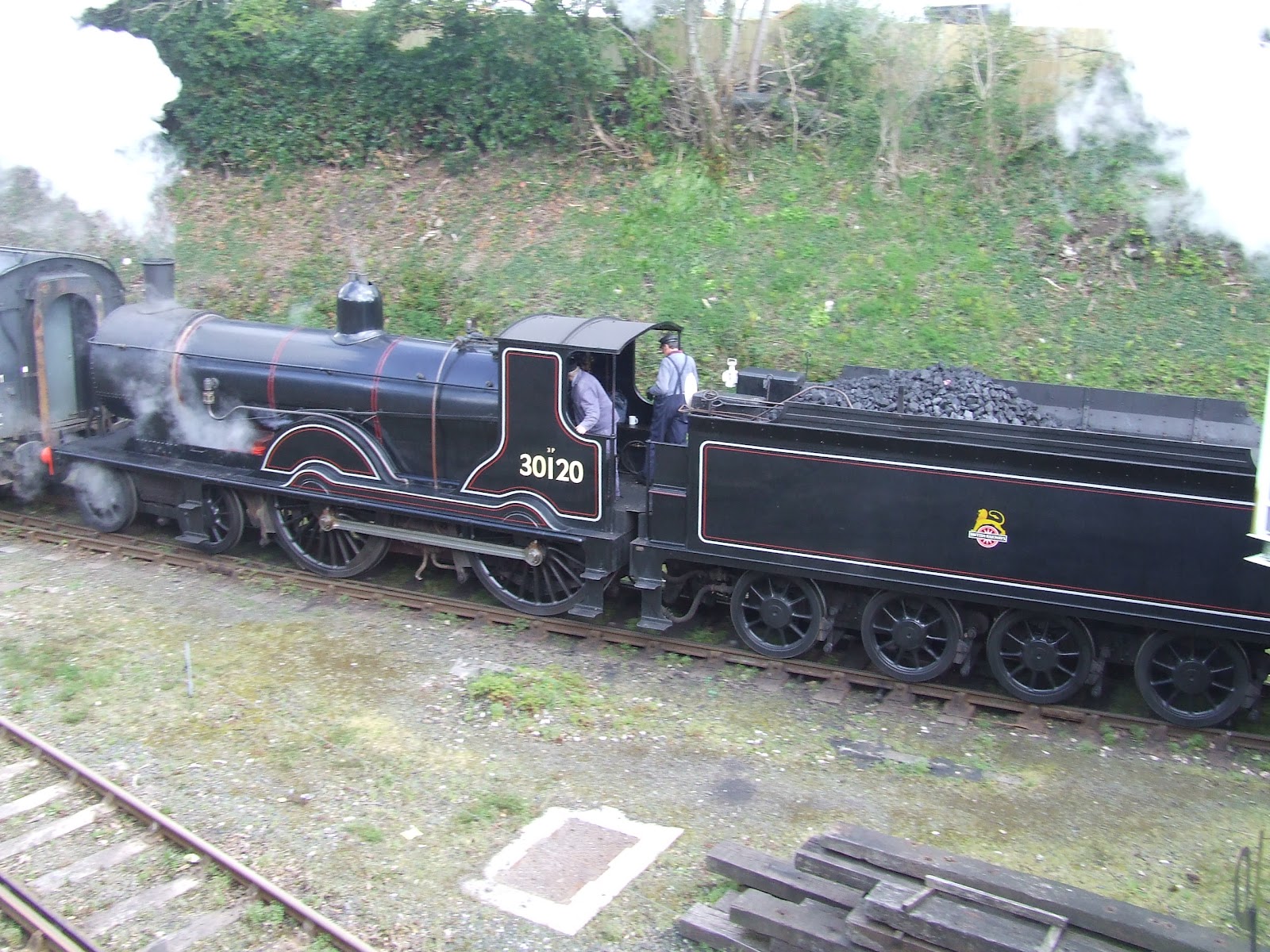
We have just arrived home after a very enjoyable week's holiday in Cornwall. The fact that it coincided with the Bodmin & Wenford Railway's Spring Steam Spectacular was no coincidence. When the line up of steam power included a T9, an O2, a 42xx along with a Beattie Well Tank and a 45xx, a trip had to be organised. The only drawback was that it happened to be the same weekend as Scalefour North. I had already promised to help with Fish Dock Road but luckily someone stood in for me on the Saturday. With much gratitude this enabled us visit the Steam Spectacular on Friday and briefly on Saturday morning before heading back home. A few photos follow...


30120 was on an empty stock movement at Bodmin General.

O2 and the Beattie prepare to depart for Bodmin Parkway
5552 working hard on the incline from Bodmin Parkway.
4247 on the incline from Boscarne Junction


The photo of the T9 is probably not the best one we took. I'll post a few more photos of the Steam Spectacular once we have sorted through them all.

During the week I'd taken the opportunity to do a few trips along the Camel trail, taking more photos of Grogley and the Bridges at Boscarne and Pendavey. Postings of these will follow in due course.

A tremendous bonus during the week was finding out that Andrew Jones, the owner of the cottage we were staying in, completed a survey of the line in 1972. His survey recorded how many sleepers were in each rail section; type of sleeper; dates on the chairs; and where occupation crossings were. He also took photos at regular intervals as he walked the line. During our conversations I have gleaned much information which I'm hoping I'll remember correctly. More posts will follow but I must unpack and get ready for Scalefour North tomorrow.

Sunday, 15 April 2012

Clay Wagons GWR dia 013 (part 2)

Just a quick posting to show where I am with the rebuilding of the Ian Kirk clay wagons.

I'd taken the above photo to show progress about a month ago but never did post a blog. The evening had been spent reducing the thickness of two sets of solebars, which can be seen on the relevant wagons. I'd also finished preparing five sets of MJT RCH compensation units. In the foreground can be seen a simple plasticard jig that I'd cut ready for marking the centre lines down the middle of the wagon floor and of each axle. I'm hoping this will help position the compensation units on these wagons and the other dozen or so Ian Kirk clay wagon kits I have waiting to be started.

This next photo shows the current state of play and was taken about two weeks ago. I've only progressed five of the six rebuilds as I'm short on wheel sets. Scalefour North is fast approaching where I hope to be able to replenish stocks of wheels and other items. Waiting in the wings are all the thinned down solebars for these five wagons ready to be installed.
Once I've a few more wheel sets in stock, I'll bring the sixth rebuild to the same state the the five above. I'll then make a start on a couple of the many un-opened bags of Ian Kirk clay wagon kits to bring this rake up to eight. So I hope to make a little more progress on these during May.

Monday, 9 April 2012

Power is installed

I've not posted any blog entries during the last couple of months due to the many projects I have on the go for both my model railway and wargaming hobbies. Trouble is I don't seem to be making much progress on any of them worthy of an entry in either blog. However, during the Easter break, I'd promised myself that I'd find enough time to complete the wiring of my little control panel for Tredethy Wharf and hopefully get something moving on the layout.

The only problem I had with the wiring was working out which two of the three tabs to use on the 9v DC socket. The 9v supply is supplying the power for the point motor circuits in the control panel. The first attempt seemed correct on the bench when tested with the multimeter but in practice did not supply any juice to the point motors. Eventually the fault was traced back to the socket and after some head scratching it was sorted. I've not installed any electromagnets on the layout yet but do intend to experiment with some hands free couplings. To this end I have installed five push buttons on the control panel including all wiring between control panel and the layout. Well there are only four at the moment as I ruined one with a little over zealous soldering.

After running the loco up and down for a while I found a few little gremlins to sort out. To banish one gremlin might require the re-laying of track at the far end where I've installed a continuous check rail. If I do need to re-lay this section I'll use copperclad sleepers next time. All of this section will be buried under road and a dirt track between two buildings so in hindsight the used of ply sleepers and chairs on this section was a little extravagant.

I feel a little happier after my efforts this weekend, but I'm also a little frustrated that it has taken so long to get this little layout to this stage... Anyway, onwards and upwards, I'll keep pecking away at it and one day I might even finish it...