Showing posts with label Track. Show all posts

Sunday, 6 March 2011

At last - Track laying finished

I received a parcel last week from a very kind member of the China Clay Branchlines Yahoo Group that contained a number of P4 track items. One package in the parcel contained slide chairs which are something I've been lacking. This spurred me on to try and complete the track to a point where I can start installing the wiring. Bringing the layout down into the living room over the weekend enabled me to work on a couple of bits that were a little difficult to get to where I normally have the layout erected.

And here it is ........


......at last, track laying finished...... and I hear you say "It's about b****y time as well". I can't believe it has taken me nine months just to build three points and about three yards of track......

During the last few months I've noticed that a few people paint the baseboards before laying track, wiring etc. Is this to help seal the wood from absorbing any dampness: from glues used in track-laying; scenic treatments; and/or from any damp storage conditions that the layout might experience? I'm starting to think it might be a good idea to paint the baseboards, even if it's only to tidy the layout up a little. So, a little late in the construction, I'll aim to dig out some white undercoat from the garage next weekend and give the boards a quick brushing........ Then it's time to get to grips with putting power to the track.

Sunday, 30 January 2011

Trial and (plenty of) error

Back to the track this evening and a little more trial and error with the V on the B8 point. I now hope I've produced something that will work OK. The rail seems firmly fixed, there's electrical continuity between V and wing rails and, to my amazement, a wagon will roll effortlessly through it. For the amount of time and effort I've put into building this V this is all very satisfying.


The technique I've used is to glue to the sleepers some of Bill Bedford's brass Point Slide & Special Chair etches to which I've soldered the V and wing rails. This has been the trial and plenty of error bit. Very little of the brass etches are visible either side of the rail which has tested my soldering skills to the full. I'm getting good at burning sleepers! ....... Hope the joints hold up when in use as I've only soldered one wire dropper from the V and will be relying on the brass etches to transfer the current to the wing rails. Next time I scratch build a point I might consider soldering some wire droppers on to the wing rails. The chairs around the V still need to be installed but this will be done later when I'm fully satisfied with the whole point.

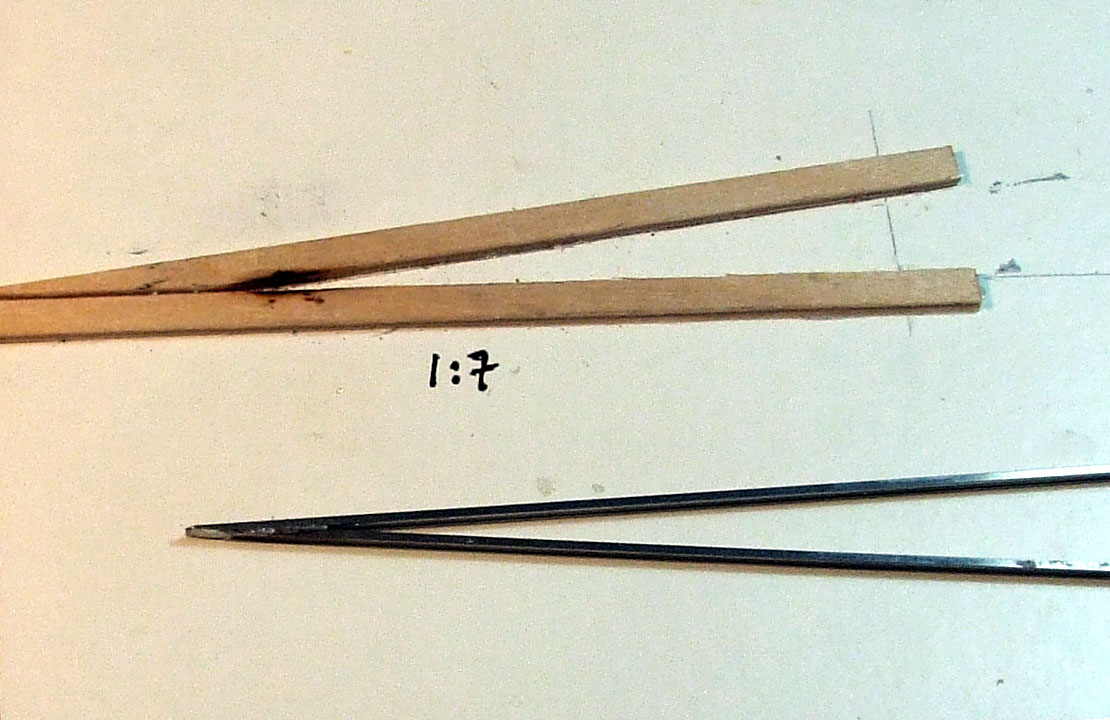
The photo below is of my trail run for constructing the switch blades and might help to explain the above technique.


The above photo shows where the brass etches will be glued to the sleepers. I'm hoping that two soldered joints will be sufficient to hold the switch blade in place. Use will be made of brass fish plates at the joint with the closure rail. This should help secure the switch blade in place and also help with electrical continuity between them and the closure rail.

Any alternative suggestions to the above will be gratefully received........

Sunday, 2 January 2011

First Crossing V

Just to while away a few moments, before going to a family event for the day, I've built my first crossing V from scratch for the final point on the layout. The previous two crossing Vs have been from the excellent P4 Track Company's kits. As this layout is just a test track I thought I'd have a go at scratch building the final point. For a first attempt, at creating a crossing V for some considerable time, I'm quite pleased with it.


Shame it's the wrong angle...... Somewhere in my head I had it that the last point was a B7 but when presenting this to the track plan, I said a non too polite word, and realised it's a B8 ......... It's a good job that practice makes perfect...... Hope to try again this evening ..............

Friday, 31 December 2010

Point operation

In the build up to this layout, point operation was always going to be one of my first major hurdles. How to set the distance between the switch blades accurately was something I was struggling with especially when working to P4 standards. My previous attempts go back a number of years to copperclad points with a sleeper sized tiebars. I now wanted a more realistic solution. I understood that the switch blades would twist slightly when moving, this movement would, in time, break any solder joint on the blade unless there was some built in flexibility between the blades and the device used to move them. Even though I'd read many descriptions of different solutions, I still struggled with how best to go about it and which materials to use. It was not until I'd discussed my problem with two guys from the P4 group that I started see how to put a solution together. Also having access to layouts in the local area group has helped, I've been able to look, listen, and hopefully, learn.

My method is nothing ground breaking, all ideas have been borrowed from other modellers. I decided at an early stage to adopt Tortoise point motors and install all motors under the baseboard using Exactoscale's Tortoise Mounting Plates which gave me the horizontal motion. I just needed to decide on how to transfer this horizontal motion vertically through the baseboard to the switch blades.

Also a couple of guys stated that on their P4 layout they used 16.5mm as the distance between switch blades. This sounded too narrow to me but in checking dimensions it seemed OK for the centre to centre measurement between blades. My rough calculations are - P4 standards state a distance of 17.47mm between outer faces of the check rails - in reality on my points this has become 17.38mm - minus 0.9mm for width of rail gives a nominal 16.5mm. No doubt purists will put me right but at the moment it seems to work for me.

Hopefully the diagram below will help to explain the following verbal description.

I've used 0.5mm brass wire for the wire droppers soldered to the blades. Both wire droppers are bent slightly so that they are vertical to the centre of the blade when they pass though the baseboard. I then drilled the motion arm from the Tortoise mounting plate with two 1.5mm holes at 16.5mm centres. The hole was drilled to pass though the arm. Into each hole I then glued a 13mm length of 1.5mm brass tube. An 18mm length of 1.0mm brass tube, with an internal dimension of 0.5mm, was then soldered into the 1.5mm tube (18mm being the distance from the base of the motion arm to the top of the balsa wood track base). When installed, this will leave just the 0.5mm brass wire passing though the ballast layer. To help with installation when threading the motion arm onto the wire droppers under the baseboard, I cut the wire droppers to different lengths, 24mm and 22mm. When fitted, the wire droppers will protrude through the motion arm which means that the motor cannot be directly under the point but will be offset to one side of the point under the baseboard.


Elements described above ready for installation.

It is all very simple really..........that is, once you know what to do, what to use and how to use it.

Friday, 29 October 2010

Track at Baseboard Joints (part 2)

A further report on method 3 from my previous posting......

Not sure if this has been done before but it is only a twist on the plywood and rivet method. At the baseboard edge, holes have been drilled through the plywood sleepers, and through the balsa underlay into the plywood track base. Then 20mm long panel pins have then been pushed and lightly tapped into place.

Panel pins in place

Pin heads were cleaned with a light rubbing of a file and then tinned with a little solder. The underneath of the rail was also cleaned with a file and tinned before soldering the two together. I still need to apply cosmetic chairs to cover the joints. My soldering technique has been a little dodgy of late but after a little demonstration the other evening from a P4 area group member (Gordon), I'm hopeful that these joints will hold.

The start of the next point with chairs and rail in place.

As can be seen from the above photo, I'm going to trial plastic chairs glued directly to plywood sleepers on the opposite side of the baseboard joint to this point. If these fail I can always revert to another method..............

Saturday, 16 October 2010

Track at baseboard joints

On arriving home yesterday evening I had the surprise of finding a nice bulky envelope containing two Ultrascale wheel conversion packs. One for another Bachmann 8750 Pannier (to be 4694) and other for a Bachmann Class 08 Shunter. Better get my next order placed......... AND place my order for some 08 cranks that are being etched by my local P4 area group (Hi guys... could I have three sets please?).

As for progress on the layout............. my evening modelling time has again been difficult to find recently but track laying is progressing on the plank, all be it very slowly. One thing I've been struggling with is how to secure track at baseboard joints. I've been mulling over options and it looks like I'm going to trial at least three different methods.....


Method 1) At the joint at one end of the layout I'm trying C&L's Baseboard End Track Protectors. They look like they will work well but I'm a little concerned about the width of these protectors and the difficulty in disguising them. At the end I've chosen they are the perfect width for soldering the running rail and check rail to. This end they will also vanish under a covering of hard standing. I may be able to disguise them at the opposite end of the layout but at the middle joint I'm not sure how I can without extending the hard standing area across the baseboard joint.


C & L Baseboard end track Protectors (C1012)


Method 2) One suggestion that has been made by a member of my local P4 group is copperclad sleepers and brass chairs. At the moment I'm not that keen as, so far, no matter how hard I've tried I have not yet been able to paint a copperclad sleeper to match the wooden ones. I'm still going to give this method a trial on the layout though.


Brass chairs and copperclad sleeper


Method 3) I'm also thinking about hammering some panel pins into the plywood track sub-base through pre-drill wooden sleepers. Rail can then be soldered to the head of the pin and cosmetic chairs applied.


Pin and rail test solder

I'm now going to set myself up to be shot down in flames by all those who have much more experience than me. So here goes............


Method 4) With all the above said I still have a thought about using plastic chairs glued to wooden sleepers at baseboard joints. My theory is.....as the glue joint between chair and sleeper will be a weak point any damage should at least leave the sleeper and ballast intact. The above three methods would possibly stand rougher handling but any damage might be drastic. Not only would there be damage to rail and chairs but there might also be damage to sleepers, ballast and possibly the balsa underlay. With plastic chairs any damage should only require the rail and any damaged chairs removed then new rail and chairs installed. Hmmmm..... not sure if I'm brave enough to give this a try though................ I'll wait for the sound of those guns being fired..........


Hopefully with the longer evenings setting in I'll manage a few more hours each week and a few photos of my meagre progress.


Sunday, 28 June 2009

A7 point kit

Where has this week gone...? It doesn't feel like over a week since I started this point kit. This weekend being first opportunity to pick this kit up again since the 18th. Thought I would put up a few more photos showing progress.... mainly for anyone who does not know these kits, or is hesitant about having a go.

This is what you get in the kit.

I had already started to solder a wire dropper onto the V before taking this photo. As with the previous kit I found the instructions to be daunting, along with seeing all the small chair components. When seeing the kit laid in the above photo there doesn't seem much to it.

I was not happy with using the plastic sleepers on the first kit. This must be something to do with reading Ian Rice's books on track construction and his use of ply and rivet construction, also due to my early results in staining wooden sleepers. I have been very pleased with the stained plywood sleepers and think I will find it very difficult in achieving the same result using plastic. So picking up from my last blog on this point kit I discarded the plastic sleepers.

I have purchased Templot software to help design the track plans for these projects and find it an intriguing piece of software. I thought I'd build this kit over a Templot template using wooden sleepers.

Above photo shows the V in place and so far so good. The plastic chairs seem to be sticking to the wooden sleepers well.

Apart from the sleeper spacing and overall length being different between Templot and the kit, there is also a difference where the V to closure rails end and start. I only realised this once the V was fixed. Don't think this will affect the points operation just the visual look. It was not until later that I spotted Martin's comments attached to my previous blog and read the form entries on this link to RMWeb.


This photo is showing the closure rails going in place.


Next day (Sunday morning) and daylight.... switch assembled.

At this point other events took control of the day. Not sure when I'll get back to this kit but hope to finish it during this next week. I've taken note of a comment re the check rail. It is thought that making the check rail live improves running though the point, something I hadn't thought of with these kits. Coming from Paxolin sleeper construction this was never a problem.

Being new to P4 standards (I really consider myself a novice to railway modelling - full stop), the questions that have been thrown up regarding these kits accurate are beyond me for the moment. Using these kits as supplied enables anyone to make a very functional P4 turnout that certainly looks the part. Exactoscale have got to be commended in bringing P4 standards closer to the masses. Beautifully made they give anyone, with a modicum of kit building experience, the capabilities of building P4 track. I need to finish the kit before deciding which standard to follow, Templot (reality) or Exatoscale (functionlity). In the end there will be few people that will be able to notice the difference. It will all be down to me accepting any inaccuracies.

Thursday, 18 June 2009

Ultrascale order but more to the point

My Ultrascale order has arrived : P4 wheel conversion packs for a Bachmann Pannier and a Class 29. Hmmm ........ which one to tackle first.

While I am now excited by the thought of quickly having a P4 loco, I am also bathing in the success of the B7 point kit. So this evening I've made a start on the A7 kit but using wooden sleepers.

Templot template PVA'd to 3/16th balsa with the pre-stained sleepers.

Templot's sleeper spacing or the length of the point does not match the P4 Track Company's kit. Not sure that this will cause too much of a problem. I hope to be using Templot to build other points and the rest of the track so this should be a good starting point .... sorry about the pun.

All ready for tomorrow night...!

More posts will follow along with photographs hopefully in the next few days......
.............................
Sorry .... just noticed that posting date for this blog was wrong not sure how I manage to post this before I'd started doing it!! Amended posting date to 18/06/09 (20/06/09).

Tuesday, 16 June 2009

At last I've built it


Last night I finally finished my first B7 P4 Track Company point kit. I'm really pleased with the result and the crossing V seems to be OK. Ran a couple of wagons through the crossing V with no problems, nice and smooth. I still feel the V is out of specification but this does show that there are some tolerences within P4. Next test will be a six coupled loco.


I only broke one fishplate and lost one very small part chair component from the switch assembly. I also seemed to be two slide chairs and three S1 chairs short. Replaced most with spares that come on the sprues but had to resort to some C & L S1 chairs to finish the job. There are a few chairs that may need tweaking in the future but at the moment I am just pleased I've got this far.


Next task it to work out how to weather the sleepers to match the wooden ones I'm producing for the plain track. My first attempt is not good need to rethink colours and how to apply the paint. I also need to think about how to operate the point. Tortoise motors seem to be the favoured option and I've purchased a pack of P4 Track Companies base plates. Just need to purchased some motors.

Overall I think these kits are superb and more will be purchased, just a shame that the sleepers are plastic and not wooden.

Monday, 13 April 2009

Ballasting (3)

"What type of ballast are you going to use?" was a question asked and to be honest, though I have several published colour photos of the branch, due to potential colour casts in reproduction I was still unsure to type and colour.

After posting a thread on RMWeb I've been informed that the likely source for the ballast during S.R. days would be Meldon Quarry on the edge of Dartmoor. If anyone else in interested the three links below offer a reasonable background information about this quarry and include photos.


If there was any ballasting completed after being transferred to WR, Stoneycombe quarry would possibly have been used.

I'm still trying to track down if any of the branch was re-ballasted during the 1950's and 1960's but I am now more confident about the colour of two photos on this website taken in 1986. To me this looks like ballast from Meldon. But I do believe ColourRail have a number of slides of this branch which I am also going to try and purchase as reference.

The thread on RMWeb is still running so more information may well surface.

Friday, 3 April 2009

Track - First effort

Spent this evening watching Ethan Hunt (Tom Cruise in Mission Impossible) with a drop of Laphroaig to keep me company. Then looked down at my workbench and discovered I'd finished my first bit of track. Just a short 14 inch length to get me started but it looks OK. There is always room for improvement, some of the chairs are at a jaunty angle and I need to work out the correct rust colour for track and chairs. Tried pre-painting the chairs using acrylics and they have taken some colour but not happy as I'm after a dusty colour.


Think I read recently that P4 Track Company's wooden sleepers are thicker than those supplied by the EMGS, which would certainly help with ballasting. I do like the texture and overall effect of the wooden sleepers so will have to give these thicker ones a try.

So far the chairs seem firmly bonded to the wooden sleepers. Will the bond reduce in time? Will the bond be strong enough to construct points? Questions I hope to be asking this weekend at ScaleFour North. Also need to purchase a point kit to see if I have the skills needed. It will be good to try plastic sleepers just to see how they turn out......Try my hand at swimming with the current before continuing swimming upstream again.

Sunday, 29 March 2009

Ballasting (2)

At last, I think I'm getting somewhere.

I've been struggling and getting very frustrated with ballasting this small length of track. Basically the ballast has not been sticking. When trying to add more ballast to repair / fill in the gaps, it's become too bulking. I have not been getting it right at all. My aim was to ballast the track so that the sleepers were not buried, but the thickness of sleepers only gives me approximately one layer of ballast grains to achieve this. The problem I was having is that with a thin layer of ballast I could see the white of the track bead coming though making the ballast look too thin (which is is). Question; how do I add depth to this thin layer?


What a mess

Cannot see very well in this photo but, along with the big gaps, there are small white gaps that are causing me the problems.


I don't know why I should be having these problems and I haven't seen any railway article with my solution but I doubt it is original. It has been born out of my wargaming experience. To add depth to painted miniatures, buildings and vehicles I use a black undercoat. This helps to create shadows and brings out the relief of the castings. Could I use this idea to add depth to a thin layer of ballast?

First trial - Much better

I think it has worked. When view from above there is no white showing though. Any small gaps between the grains is black which is creating depth / shadows. Next step is to see if I can repeat this over a longer length.


Not only a much neater result, as I not putting so much glue down, but no small white gaps.

Result

To me the last photo looks near perfect. A permanent way gang might be pleased with that. The ballast seems flat and no unsightly lumps, and the sleepers are slightly proud of the ballast.

I now need to decide whether I paint/spray the chairs and rail before I glue them to the sleepers of after glueing. Decisions, decisions.

Wednesday, 25 March 2009

Ballasting (1)

This is what I used to like about this hobby, there's always some challenge at each stage. I would never have thought ballasting track would have been one of them though. Many of you out there will no doubt be asking "what am I playing at". Even though I've been a railway modeller in the past it was so long ago that I am realising I've got to consider myself a complete beginner. Learning again from scratch all over again.

I've been hanging on to a length of kitchen cupboard beading for years thinking it would make an ideal mount for a display. A rummage thought the garage and out it came. Glue some track to it ballast it and way I go. Sounds simple and I suppose it would have been if I'd purchase some nice P4 flexi track. Why do I do things the hard way?

I've also met with my local ScaleFour Group recently and they suggested using balsa wood as a track base. Cork would have been my first choice but apparently balsa is better than cork for acoustic qualities and deadening sound transmission through to baseboard. Not really necessary for this first metre but start as I mean to go on. So a quick purchase of balsa which was glued to the beading board, a metre length of straight track printed from Templot glued to the balsa and away I go.

I took Ian Rice's advice and decided to ballast the track before gluing chairs and rail in place. Quickly realised that without the punch holes or rivets in the sleepers I would loose the position of rail centres. Plan is to lay sleepers in batches and lightly pencil in rail centres onto sleepers as I go along.

First attempt and not happy..... ballast was lightly tamped down and left over night. When excess was tipped off (not brushed nor scraped) I was left with the above mess. Was this too much to do in one go? Was the glue going off? Was the glue not wet enough? Was the glue not thick enough (in depth)? Should I have added a drop of washing-up liquid?

Second attempt and getter better, reduced the quantity of sleepers laid in one go to four so glue will not go off so quickly but it is still not as good as I expected. But the glue should not be going off in such a short time, must be quantity of glue.

That's better... at least I have covered all the paper in this last attempt. This was just by putting a little more glue down, looked to be too much as it was starting to obscure the sleeper positions.

Onwards and upwards ..... just the thick end of a metre to go and I can start glueing chairs and rail.

Sunday, 22 March 2009

Making a start

At last I feel like I have made a start. Purchased some plywood sleepers and chairs along with P4 gauges from the EMGS. These arrived a few days ago. My intention is to trial gluing the plastic chairs to wooden sleepers.... I can hear the comments already....

First trials indicate that MEK does not give a strong enough bond, but Butonone and Super Glue seem to. Using the finger and nail test I cannot shift the chairs once the bond has taken. So I'm going to build a yard of track and see how I fair.


Next task, cutting the plywood into 34mm sleeper lengths. It was here when I asked myself, "why didn't I purchase the ready cut lengths?" My thought was that if using glue as the main bond I didn't want he pre-punched hole reducing the surface area for the bond. I can see that this task is one for a evening when I'm brain dead.


Next task staining. I'd moved downstairs and and tackle this first thing in the morning in daylight hence the change in lighting in the above photo. I've followed one of Iain Rice's techniques, using a mix of water, isopropyl alcohol, and india ink. After a few trials I've ended up with a mix of 100ml of water, 50ml of isopropyl alcohol, 4ml of black india ink and 5ml of sepia india ink. I was trying to match the colour of sleepers in colour photograph of Bodmin North. At the moment they look close to the colour I'm after. No doubt once I've laid and ballasted the track the colour will look different , for better or worse I will have to wait and see.

Next stage, my first yard of track. Lets hope the chairs will stick to the stained sleepers. More postings will follow.

Wednesday, 26 November 2008

Track - Sleepers and Chairs and other stuff

I'm nearing the point of placing an order for track components so need to put some thoughts down to the type of sleepers and chairs that I'm going to use.

Sleeper type, plastic or wood?
Wooden sleepers would be my preference as I feel they will give a more natural feel to the track work. On the other hand as I have not built any track for some considerable time A plastic kit might be a good starting point (no pun intended). At this moment, in drawing the track plan, there would not seem to be many points at Grogley that suit an of the standard "out of the box" kits. The main junction will have to be bespoke.

This has started me thinking that I may build a little 6 x 1 ft test layout using a couple of kits and then building a couple of bespoke points using wooden sleepers. This would give me a chance to iron out any problems before embarking on the main project.

Sleepers size and length?
My understanding on the sleeper wide is 10" for plain track, 12" for turnouts. But were 12" sleepers used on joints on plain track? Regarding length, as the track had been relayed at least twice before the 1960's the sleepers should be 8'6" long.

Chairs, Standard 3 bolt or LSWR?
From photos it looks like Wadebridge had the standard 3 colt chair in 1959, though the Wenford Bridge branch still had the LSWR chairs in 1962. As yet I have not been able to confirm Grogley after 1933 when it still had LSWR Chairs, but it looks like Boscarne had the standard chair in 1962. So I've settled on the standard 3 bolt "S1" Chairs for the main running lines though the junction. (That is 1 bolt on the outside and 2 bolts inside).

A cat among the pigeons
With all the above said I have I've seen a colour slide that looks like Dunmere junction may have had concrete sleepers in June 1960. I am also certain I have a B/W photo somewhere of the junction outside Wadebridge circa 1960 that seemed to showed concrete sleepers on the Bodmin section. Makes me think:
Q1) I could justify laying the plain track leaving the junction towards Bodmin with concrete sleepers?
A1) I think the answer to the above question is yes but no. After reading Colin Craig's article, mentioned below, I feel that with no detailed information as to the exact type of concrete sleeper and rail used on the branch I cannot justify any on the model.
Q2) So when did BR introduce concrete sleepers and on what lines first?
Q3) Were concrete sleepers laid on branch lines first as tests before being used on mainlines?
Q4) When did flat bottom rail start to be used....was this at the start of the introduction of concrete sleepers?
All of the answers to the last three questions above can be found in an excellent article by Colin Craig from the MMRS at http://www.mmrs.org.uk/technical/track.html